decay modes for motor p and n chanel h-bridge Decay is the re-circulation of current within a motor driver that uses pulse-width modulation (PMW). The inductive nature of DC motors means that they will oppose any change in the current run through them. The new District PM messenger bag, with its modern rectangular silhouette and functional size, is a fantastic everyday bag. Fashioned from deep-dyed Taiga leather, it features a zipped back pocket and an adjustable strap, for shoulder or cross-body wear. The strap has a D-ring to hang keys or a wallet.
0 · slow decay motor h bridge
1 · motor h bridge decay mode
2 · motor h bridge decay
3 · h bridge slow decay
4 · h bridge fast decay
5 · h bridge decay mode
6 · dc motor decay mode
7 · current decay mode pdf
Discover the Finest Town Hall 8 War Base Links, Masters of Defense Against Dragons, Gowipe, Hogs, and Valkyries. These Anti-1 Star and 2 Star Town Hall 8 Layouts excel at guarding against any attack.
decay modes for motor p and n chanel h-bridge*******This document explains current recirculation techniques in a motor driver, why it is important and how they are implemented with TI's integrated motor driver decay mode .Decay is the re-circulation of current within a motor driver that uses pulse-width modulation (PMW). The inductive nature of DC motors means that they will oppose any change in the current run through them.

This document explains current recirculation techniques in a motor driver, why it is important and how they are implemented with TI's integrated motor driver decay mode circuitry.
h bridge slow decay Fast decay mode causes a rapid reduction in inductive current and allows the motor to coast toward zero velocity. Slow decay mode leads to a slower reduction in inductive current but produces rapid deceleration.
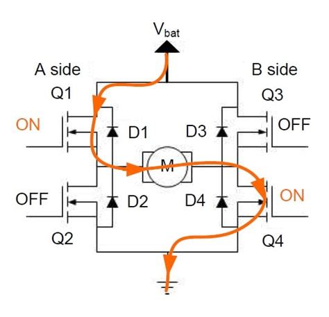
Decay is the re-circulation of current within a motor driver that uses pulse-width modulation (PMW). The inductive nature of DC motors means that they will oppose any change in the current run through them.In 'fast decay' mode, the current flows through the FET body diodes to the rails, and from there into the power supply capacitors, briefly ramping the supply voltage up a little (called 'supply pumping'). The supply voltage is available to reduce the inductor current.decay modes for motor p and n chanel h-bridge h bridge slow decayThese MOSFETs can be either P-Channel or N-Channel depending on the design requirements for any specific application. An example of an all N-Channel MOSFET H Bridge is shown in Figure 2 to the left. Let's pretend we have a standard 4 MOSFET H-bridge that controls a 12V brushed DC motor. When driving the motor forward, we can keep SW4 on continuously and pulse SW1 on and off (see below image).

Objective: control. Direction of Rotation. Speed / Torque. Forward: Vary voltage to set speed. E.g. 6V à full speed, 3V à half speed. Reverse: Flip terminals: e.g. -6V.The DRV8841 supports three different decay modes: slow decay, fast decay, and mixed decay. The current through the motor windings is regulated using a fixed-frequency PWM scheme.The DRV8821 supports two different decay modes: slow decay or mixed decay. The mixed decay mode uses slow decay on increasing steps and mixed decay on decreasing steps.
Brushed DC Motor 2: The H-Bridge. What is an H-bridge? - Drawback is that the gate is driven 5-10 V higher than the source. - Once the current is flowing in Forward direction, the direction of the current is maintained by the inductance of a Brushed DC motor.
This document explains current recirculation techniques in a motor driver, why it is important and how they are implemented with TI's integrated motor driver decay mode circuitry.decay modes for motor p and n chanel h-bridge Fast decay mode causes a rapid reduction in inductive current and allows the motor to coast toward zero velocity. Slow decay mode leads to a slower reduction in inductive current but produces rapid deceleration.Decay is the re-circulation of current within a motor driver that uses pulse-width modulation (PMW). The inductive nature of DC motors means that they will oppose any change in the current run through them.In 'fast decay' mode, the current flows through the FET body diodes to the rails, and from there into the power supply capacitors, briefly ramping the supply voltage up a little (called 'supply pumping'). The supply voltage is available to reduce the inductor current.These MOSFETs can be either P-Channel or N-Channel depending on the design requirements for any specific application. An example of an all N-Channel MOSFET H Bridge is shown in Figure 2 to the left.
Let's pretend we have a standard 4 MOSFET H-bridge that controls a 12V brushed DC motor. When driving the motor forward, we can keep SW4 on continuously and pulse SW1 on and off (see below image).Objective: control. Direction of Rotation. Speed / Torque. Forward: Vary voltage to set speed. E.g. 6V à full speed, 3V à half speed. Reverse: Flip terminals: e.g. -6V.The DRV8841 supports three different decay modes: slow decay, fast decay, and mixed decay. The current through the motor windings is regulated using a fixed-frequency PWM scheme.
LOUIS VUITTON
decay modes for motor p and n chanel h-bridge|h bridge slow decay


